How to Read Electrical Drawings: Part 3 | Fire Alarm & PA Layouts
How to Read Electrical Drawings: Part 3 | Fire Alarm & PA Layouts
In the third part of our series on “How to Read Electrical Drawings,” we delve into the details of Fire Alarm (FA) and Public Address (PA) system layouts. This knowledge is essential for electrical engineering, construction, and maintenance professionals. It empowers them to ensure the safety and seamless communication infrastructure of buildings. Here, we’ll discuss the key symbols, components, and their strategic integration that constitute the foundation of these dynamic electrical layouts.
Fire Alarm & PA layouts
Fire Alarm and Public Address (PA) layouts often fall under the “Low Voltage” or “Signal and Control” category in electrical plans. These drawings focus on systems operating at a lower voltage than power distribution systems. The low voltage category includes various systems like fire alarms, PA systems, security systems, and other control and signaling devices. Understanding these layouts is crucial. It helps you grasp how low-voltage systems are strategically designed within electrical plans. This insight is required for integrating elements vital for emergency response and public communication.
Fire Alarm Components
Fire alarm systems play a critical role in ensuring the safety of occupants in any building. A clear understanding of their layouts is essential for both design and troubleshooting purposes. To comprehend the layout, the following are the main components of a fire alarm system:
Detector (Smoke, Heat, Duct, Beam, etc.)
Multi-Detector
Reflector
Sounder
Relay Module
Control Module
Monitor Module
Manual Call Point
Response Indicator
Sprinkler Flow Switch
Power Supply Unit
Fire Alarm Control Panel
Emergency Communication System
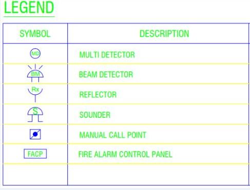
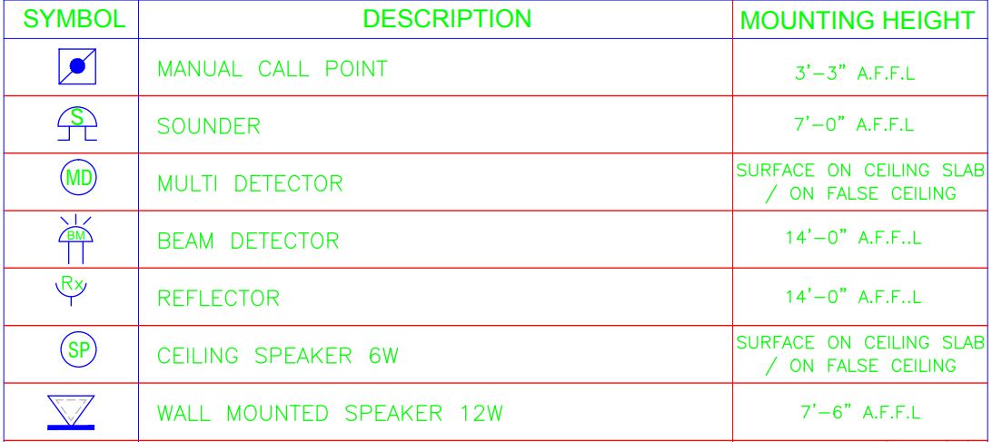
Fire Alarm Symbols
Electrical drawings utilize symbols to represent various devices and elements. Part 1 of our series will guide you through common symbols associated with construction drawings. Understanding these symbols is a key step in interpreting the drawings accurately. Fire alarm schematics often feature a legend table located in the top right corner of the drawing. This table includes symbols utilized in the schematic, accompanied by descriptions detailing their meanings. Below are some of the common symbols used in fire alarm layouts:
Fire Alarm SymbolsLegend
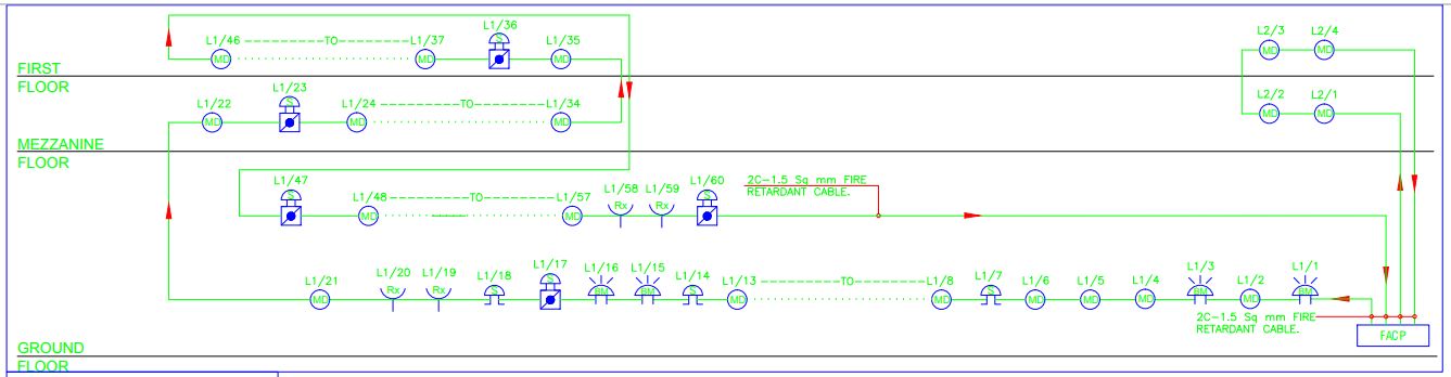
Fire Alarm Schematic
A fire alarm schematic refers to a diagram or drawing that represents the electrical and functional components of a fire alarm system. It provides a visual representation of how various devices, such as detectors, alarms, control panels, and signaling devices, are connected and interact within the system. The schematic typically uses symbols to represent different components and illustrates the pathways of electrical connections.
Different types of fire alarm systems exist based on their wiring and connections. In the fire alarm schematic diagram given below an addressable fire alarm system is shown. Within this diagram, the system is designed with two loops, effectively covering three floors of a building. The components include a Fire Alarm Control Panel (FACP), Multi-Detector (MD), Beam Detector (BM), Reflector (Rx), Sounder (S), and Manual Call Point (MCP). For a detailed understanding of each symbol, please refer to the provided legend table.
Click the image to enlarge
Public Address Layout
A Public Address (PA) layout refers to the arrangement or design of a system used for making announcements or broadcasting messages to a large audience in public spaces or buildings. The layout typically includes various components such as microphones, amplifiers, speakers, and control panels strategically placed throughout the area to ensure clear and effective communication. Public Address systems are commonly used in settings such as schools, airports, train stations, stadiums, and commercial buildings to convey important information, announcements, or emergency alerts to people within the vicinity. The layout is designed to ensure optimal coverage and intelligibility of the messages being broadcasted to ensure that they reach the intended audience clearly and effectively.
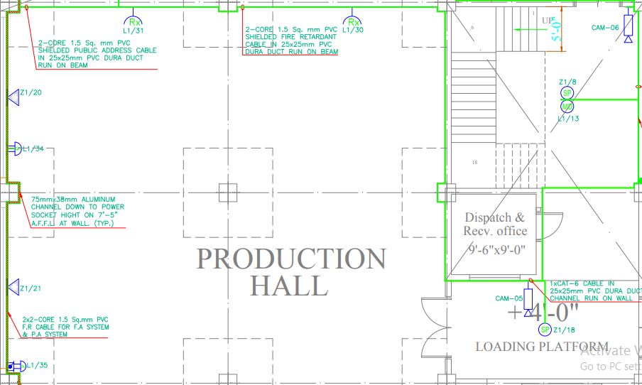
Public Address and Fire Alarm Integration
In electrical drawings, Public Address (PA) systems are integrated alongside fire alarm systems to ensure comprehensive safety and communication infrastructure. This involves overlaying the layout of the PA system onto the electrical drawings, often on a separate layer or section. To ensure seamless operation, wiring diagrams are then generated to illustrate how the various components of both the fire alarm and PA systems are interconnected. By doing so, designers ensure that all devices are correctly wired and integrated into the electrical infrastructure. In modern systems, both fire alarms and PA devices may have unique identifiers or addresses, making them addressable. The electrical drawings include these addresses for each device, simplifying programming and troubleshooting processes.
In the diagram given below, an addressable FA and PA layout is shown along with the legend table.
Click the image to enlarge
Conclusion
To approach Fire Alarm (FA) and Public Address (PA) drawings systematically, begin by identifying the legend, which provides explanations for the symbols used in the drawings. Next, trace the circuits to understand how various components are connected and interact within the systems. Pay close attention to the flow of information, such as the pathways of wiring and communication signals, to comprehend the overall functionality of the FA and PA setups. By following this step-by-step approach, you can gain valuable insights into interpreting complex layouts effectively and accurately. This knowledge not only ensures the safety and communication infrastructure of buildings but also contributes to efficient and reliable emergency response mechanisms. As technology evolves and systems become more integrated, a solid grasp of interpreting FA and PA drawings will remain a valuable skill for professionals in various industries.
A dedicated Electrical Engineer with expertise in ISO auditing and a strong passion for sharing insights into the electrifying world of design. With over 5 years of diverse experience, I’ve powered through projects ranging from the manufacturing industry to building construction. My skillset extends to automation building design, where my meticulous electrical drawings ensure precision and attention to detail.


")


