How to Read Electrical Drawings: Part 1 | Electrical Symbols
How to Read Electrical Drawings: Part 1 | Electrical Symbols
Understanding electrical drawings is super important in the world of electrical engineering and design. These drawings are like a special language that helps us turn ideas into real electrical systems. In this first part of our series, “How to Read Electrical Drawings,” we’re diving into the basics – electrical symbols. Like the alphabet in language, these symbols convey essential information, enabling professionals to understand and communicate the intricacies of circuits, components, and systems.
Electrical Symbols
Electrical symbols are visual representations in electrical drawings and diagrams to convey information about components, devices, and connections within a circuit or system. These icons serve as a standardized and universally recognized language that engineers, electricians, and technicians use to communicate and understand the design and layout of electrical systems. Each symbol represents a specific electrical element, such as a resistor, capacitor, switch, or power source, allowing professionals to create accurate and universally understood diagrams. By using them, individuals can effectively convey complex information about the configuration and functionality of electrical circuits without the need for detailed written explanations.
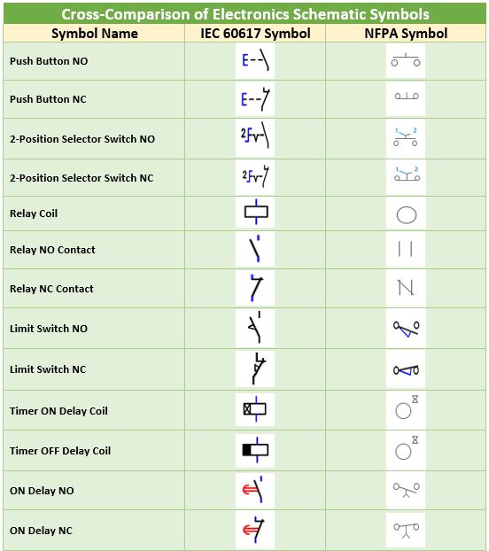
A Cross-Comparison of Electrical & Electronics Symbols
In exploring electrical and electronic icons, we embark on a cross-comparison journey, delving into the variation of symbol design. Our showcase uncovers a selection of symbols meticulously sourced from the AutoCAD Schematic Library, aligning with the standards set by NFPA and IEC 60617. This visual demonstration provides a firsthand look at how these icons manifest in different design contexts, offering insights into the subtle variations that define the universal language of electrical and electronic schematics.
Unveiling the significance of symbols, we now explore their role in construction drawings, elucidating the universal language they provide for clear and efficient communication.
Why are symbols used in Construction Drawings?
Symbols are essential in construction drawings, particularly in electrical plans, for their ability to convey complex information efficiently. These visual representations simplify design details, ensuring clarity and consistency across projects. Symbols provide a universal language, transcending language barriers and facilitating international collaboration in the construction industry. With their space-efficient and easily interpretable nature, symbols play a crucial role in enhancing the overall efficiency of design, planning, and communication in construction projects.
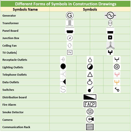
Common Electrical Symbols in Construction Drawings
Transitioning into practical applications, we’ll spotlight different forms of common electrical symbols frequently encountered in construction drawings, providing insights into their widespread usage and interpretation.
In conclusion, mastering the art of reading electrical drawings requires a comprehensive understanding of electrical symbols, from their fundamental representation to the variations in electronic symbols. The cross-comparison of symbols enhances our visual literacy in electrical and electronic schematics. Recognizing the pivotal role of symbols in construction drawings, we’ve uncovered their significance as a universal language, facilitating design interpretation across the diverse landscape of the construction industry. Embrace the art of decoding diagrams, unlocking a new level of proficiency in your projects. Stay tuned for more insights and practical knowledge in Part 2 of our series.
A dedicated Electrical Engineer with expertise in ISO auditing and a strong passion for sharing insights into the electrifying world of design. With over 5 years of diverse experience, I’ve powered through projects ranging from the manufacturing industry to building construction. My skillset extends to automation building design, where my meticulous electrical drawings ensure precision and attention to detail.