How to Read Electrical Drawings: Part 2 | House Wiring Diagram
How to Read Electrical Drawings: Part 2 | House Wiring Diagram
In the second part of our series on “How to Read Electrical Drawings,” we delve into the details of house wiring diagrams. Understanding the blueprint of electrical systems within a home is fundamental for homeowners, electricians, and DIY enthusiasts alike. In this comprehensive guide, we will unravel the layers of information embedded in house wiring diagrams, empowering you to decipher and interpret electrical plans confidently.
House Wiring Diagram
A house wiring diagram is a visual representation that illustrates the electrical layout and connections within a residential property. These diagrams typically include details about the main distribution panel, individual room circuits, appliance connections, and safety features like fuses or circuit breakers.
Understanding Room Circuitry from Utility to Switchboard
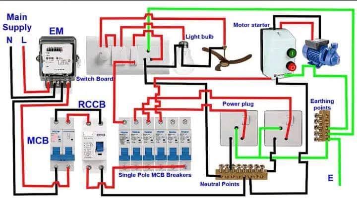
The electrical power supply from the local utility grid or electrical service provider typically comprises four main lines: the three phases and the neutral. Upon entering a house, this power is commonly metered by a utility meter installed at the point of entry. This meter is then linked to the main electrical service panel, also referred to as the distribution board or breaker box. Within this distribution board (DB), one typically finds a combination of Double or Triple-Pole Circuit Breakers, Residual Current Circuit Breakers, and several Single-Pole Miniature Circuit Breakers, all essential for safeguarding the integrity of outgoing circuits.
Moving forward, the switchboard becomes the gateway to room circuiting, with wires extending from the DB. Here, switches hold the power to control individual lights within the room. The configuration of the switchboard and the placement of switches play a crucial role in the dynamics of room illumination. Continuing from the switchboard, the electrical wiring branches out to all connected loads within the room, including outlets, appliances, and additional lighting fixtures.
In the diagram below, a simple house wiring diagram is shown with a single-phase power supply.
House electrical wiring diagram
Single Room Circuiting
Single-room circuiting refers to the specific electrical circuitry within an individual room of a building. It involves arranging and connecting electrical components such as lighting fixtures, power outlets, and switches within that particular space. The circuiting starts from the Distribution Board (DB) or electrical panel, extends through the switchboard, and then branches out to various lighting points and power outlets within the room. Understanding single-room circuiting is crucial for electricians and individuals involved in electrical installations, as it ensures safe, efficient, and well-designed electrical systems within each distinct area of a building.
Device Categorization in Single-Room Circuitry
Roomwiring can be broadly categorized into two groups based on their electrical requirements. The first category includes “no load, only control” devices, like switches and dimmers, which solely regulate electricity and require only a phase wire for operation. The second category encompasses “devices carrying a load”, such as sockets, bulbs, fans, and indication lights, necessitating both a phase and a neutral line. The phase wire supplies power, while the neutral line completes the circuit, ensuring safe and efficient functionality. Recognizing these distinctions is fundamental for anyone engaged in electrical wiring, ensuring the creation of a safe and effective electrical system.
House Wiring Plan
After understanding single-room circuiting we can read complete House Wiring Plans. House Wiring Plan is a visual representation that illustrates the arrangement and connection of electrical devices, outlets, switches, and wiring within a house, providing a comprehensive overview of the electrical system’s layout and configuration. This comprehensive blueprint serves as a guide for the installation and positioning of both lighting fixtures and power outlets.
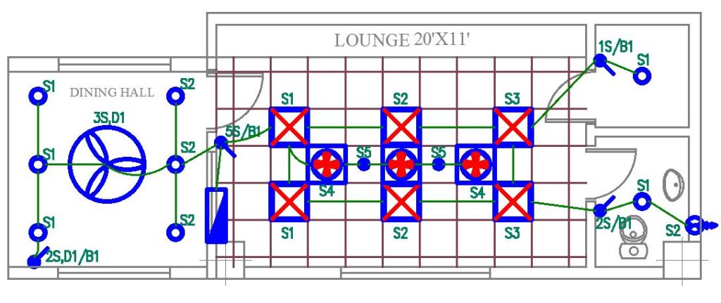
Lighting Layout:
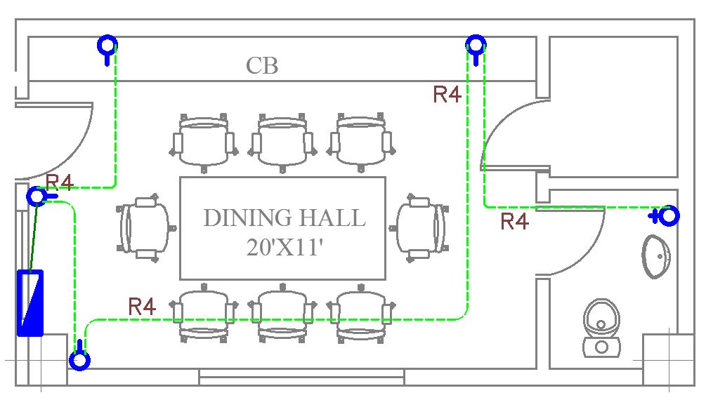
An electrical lighting layout plan details the arrangement of lighting fixtures within a building, specifying the type and location of each light, along with corresponding switch placements and wiring paths. This plan ensures effective illumination and a well-designed lighting system. In the house wiring diagram given below, we can see the light wiring in green lines.
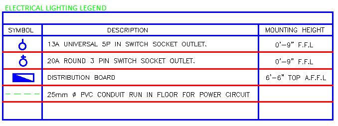
An electrical power layout plan outlines the distribution of power outlets and circuits throughout a structure. It includes the placement of power sockets, dedicated circuits for major appliances, and the wiring paths connecting outlets to the main electrical panel. These plans collectively guide electricians and contractors in efficiently installing lighting and power systems. In the house wiring diagram below, we can see the power wiring in green dotted lines.
House Wiring Diagrams can be decoded effortlessly with the following essential tips, providing a straightforward guide to understanding the configurations in your home’s electrical plans.
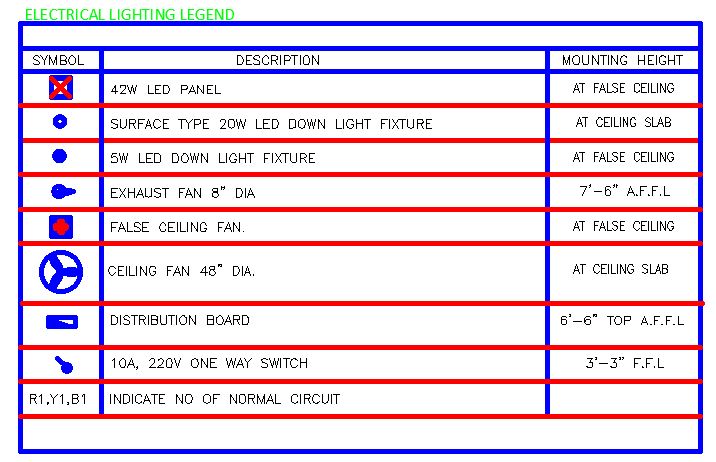
Legend Consultation:
Always refer to the legend or key provided with the house wiring diagram. It offers crucial information about the symbols used and ensures accurate interpretation.
Understanding Symbols:
Familiarize yourself with common electrical symbols used in house wiring diagrams. Symbols for switches, outlets, lights, and various devices convey specific information about their function and connectivity.
Identifying Circuits:
House wiring drawings delineate circuits for lighting, outlets, appliances, and more. Learn to identify and trace these circuits for a holistic view of your home’s electrical layout.
Color Coding:
Pay attention to color-coded lines in the diagram. Colors represent different phases or functions, simplifying the identification of wires and their roles in the electrical system.
Labeling Devices:
Devices such as switches and outlets are often labeled with unique identifiers. Learn to associate these labels with corresponding symbols in the diagram for seamless recognition.
Grasping Wiring Paths:
House wiring diagrams illustrate the paths that electrical currents follow. Comprehending these paths aids in understanding how electricity flows through your home, from the main service panel to individual outlets and fixtures.
Conclusion
As we conclude our exploration in “How to Read Electrical Drawings: Part 2,” the journey began with a detailed comprehension of a critical blueprint – the House Wiring Diagram. Navigating through the various facets, from single room circuiting and understanding the intricate path from utility to switchboard to categorizing devices in electrical wiring, we’ve unveiled the layers of complexity within electrical systems. Our exploration extended to the vast landscape of Electrical Lighting & Power Layout Plans, illuminating spaces and empowering every corner with a seamless electrical network. Finally, the tips gained in interpreting electrical house drawings have become a valuable compass for deciphering complex plans, ensuring a nuanced approach to electrical literacy. This comprehensive guide not only enhances your ability to interpret the language of electrical drawings but also equips you to implement, troubleshoot, and optimize electrical systems within the dynamic framework of homes and structures.
Also read: How to Read Electrical Drawings: Part 3 | Fire Alarm & PA Layouts
A dedicated Electrical Engineer with expertise in ISO auditing and a strong passion for sharing insights into the electrifying world of design. With over 5 years of diverse experience, I’ve powered through projects ranging from the manufacturing industry to building construction. My skillset extends to automation building design, where my meticulous electrical drawings ensure precision and attention to detail.