What is Earthing?
Have you ever noticed that sometimes you get shock while touching metal body of any electrical appliance? Did you tried to find out the reason of happening this? If you still didn’t know the exact reason of this shock you will be able to know the reason after reading this article.
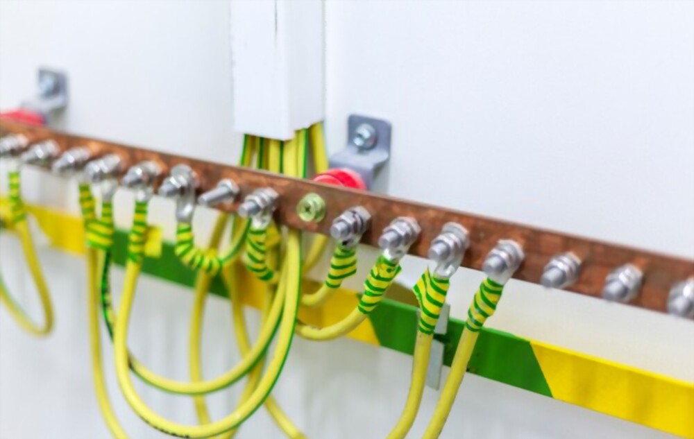
Earthing is defined as the system which can protect equipment from electrical faults and save lives by discharging fault current directly to the ground. When live wires touch a metallic part of any appliance, it will generate potential on that metal which could give a severe shock to any person who touches that metal. But if that metal part is connected with earthing system it will directly discharge it to the ground through earthing system and a person will not get shock. As a result of this, a person will not get shock due to proper earthing.
Purpose of Earthing
Electrical systems are earthed for three main purposes:
1. As a safety feature for property, equipment and life – An earthed circuit reduces the risk of death or injury by providing an alternate path for current to discharge into the ground. Appliances, Equipment, property and lives are protected against faults, leaks and fires resulting from short-circuits and sparking.
2. Protection against over-voltage – Earthing also provides protection against power surges, accidental connection with high-voltage lines and even lightning strikes, allowing the energy to flow to the ground, with minimal effect.
3. Voltage Stabilisation – The ground offers a common point of reference for calculating the relationship between different voltage sources. It’s been used as a universal standard since the introduction of the distribution system.
Read Also: What is difference between earthing and Grounding?
Conventional Methods of Implementing Earthing
There are two basic methods of earthing used in conventional installations:
1. Plate Type Earthing
One of the conventional methods of installing earthing is to bury a conductive plate in the ground and connect it to the earthing circuitry. The plate is typically installed vertically, edge-wise at a depth of 8 feet, with a galvanized iron (GI) strip running to the surface for connections. The strip typically has a cross section of 50mm X 6mm. The first four feet above the plate is filled with alternating layers of charcoal and salt, to increase conductivity and moisture retention.
The specifications of the plate vary, along with the material:
- Cast iron – 600mm X 600mm X 12mm
- Galvanised iron – 600mm X 600mm X 6mm
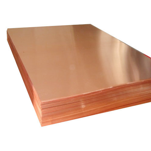
- Copper – 600mm X 600mm X 3.5mm
2. Pipe Type Earthing
Another commonly used method for installing a ground connector is to bury a pipe vertically, deep into the ground. A 10 foot long C-class galvanised iron pipe is used as the base of the ground connector, with 75mm GI flanges welded on. The flanges that are used have six holes, which are used for wiring. The area surrounding the pipe is filled with layers of charcoal, salt or an earth reactivation compound.
Constructing and Maintaining an Earth-Pit
Now a days, earth-pits are most common method for earthing, especially for electrical networks. Electricity always follows the path of least resistance. To divert the maximum current away from a circuit, earthing pits are designed to reduce ground resistance, ideally to 1 ohm. To achieve this:
- Excavation of an area of 1.5m X 1.5m X 3m.
- The pit is half filled with a mixture of Bentonite.
- The placement of a 500mm X 500mm X10mm GI plate (earth plate) in the middle.
- Filling of Pits with the coal/sand/salt mixture.
Now, To connect the earth plate to the surface, two GI strips with a cross section of 30mm X 10mm can be used, but a 2.5” GI pipe with a flange at the top is preferable. Additionally, the top of the pipe can be covered with a T-section, to prevent mud and dust from entering and clogging the pipe. In summer, the pit should be watered to keep it from drying out.
Advantages:
Advantages of the earth-pit method include:
- Wood coal powder is a great conductor and prevents corrosion of the metal parts
- The salt dissolves in water easily, increasing conductivity significantly
- Sand allows water to percolate through the entire pit
In order to test the effectiveness of the pit, check that the voltage difference between the pit and the neutral of the mains supply is less than 2 volts. The resistance of the pit should be maintained at under 1 ohm, up to a distance of 15m from the conductor.
Earth Resistivity
The resistance of the earthing system is affected by a variety of factors:
- Soil Resistance – The composition of the soil, grain size and distribution.
- Moisture – Up to 15% water content significantly changes resistivity. Beyond that, it has little effect.
- Dissolved Salts – Pure water has very low conductivity. Salt is an electrolyte that reduces the resistance when it’s dissolved in water.
- Obstructions – Nearby concrete buildings nearby or rocks in the soil underneath the earthing system can increase its resistance.
- Current Magnitude – Long periods of exposure or higher currents flowing through the earth can dry the soil in the surrounding area and increase the system’s resistance.
Measuring Earth Resistance
Megger or Earth Tester measures earth resistance. It consists of a voltage source, ohm-meter to measure resistance and spikes that are staked into the ground for measuring. You can measure the soil resistance using either the 3-point method or the 4-point method.

An experienced electrical professional having more than 8 years of experience of the industry in diverse fields of engineering including Electrical Design & Consultancy, Audit & Inspection, Execution of Construction Projects having expertise in designing of HighRise buildings, Residential & Commercial buildings, Offices, Schools, Restaurants and some Industrial projects
