Electrical drawings are the language electricians, engineers and contractors use to agree on what gets built. Once you know where to look and what the symbols mean, a set of electrical drawings is straightforward to read. This guide walks through a complete drawing set step by step: the title block and legend, electrical symbols (US ANSI/NEMA and IEC), lighting and power plans, panel schedules, single-line diagrams, and fire alarm and public address layouts.
How to read electrical drawings: the short answer
- Read the title block to confirm the project, sheet number, scale and latest revision.
- Study the legend and general notes on the first electrical sheet. They define every symbol and abbreviation used in the set.
- Start with the single-line diagram to see how power flows from the utility or transformer to each panel.
- Read the panel schedules to see every circuit, its breaker size and its load.
- Trace circuits on the lighting and power plans from each device back along the home run to its panel and circuit number.
- Check the low-voltage sheets (fire alarm, public address, data, security) separately, since they have their own legends.
- Read the details and schedules for mounting heights, fixture types and installation specifics.
Types of electrical drawings in a construction set
A typical building project has one electrical drawing set (sheets numbered with an E prefix) alongside the architectural, structural, plumbing and HVAC sets. See our list of construction drawings for how they fit together. The electrical set usually contains:
| Sheet | What it shows | Typical sheet number |
|---|---|---|
| Legend, symbols and general notes | Every symbol and abbreviation used, plus project-wide requirements | E-001 / E0.01 |
| Site plan | Utility service, transformer pad, underground ducts, site lighting | E-010 / ES-1 |
| Lighting plans | Light fixtures, switches, switch legs and lighting circuits for each floor | E-100 series / E1.x |
| Power plans | Receptacles, equipment connections, dedicated circuits and home runs | E-200 series / E2.x |
| Single-line (one-line) diagram | Power flow from source to every panel, with breaker, cable and transformer sizes | E-600 / E6.x |
| Panel schedules | Every circuit in every panel: description, breaker, poles and load | E-700 / E7.x |
| Riser diagrams | Vertical routing of feeders, fire alarm, data or PA between floors | E-600 series |
| Low-voltage plans | Fire alarm, public address, CCTV, data and access control devices | E-800 / FA / T sheets |
| Details and schedules | Mounting details, fixture schedule, grounding details, equipment schedules | E-500 / E5.x |
Sheet numbering varies between firms and countries, but the order above (legend first, plans next, diagrams and schedules last) is almost universal.
Start with the title block, legend and general notes
Before you look at a single symbol, read three things:
- Title block (bottom right): project name, sheet title and number, drawing scale, date, the engineer’s stamp and the revision table. Always make sure you are reading the latest revision. Changes are usually marked with a revision cloud and a triangle containing the revision number.
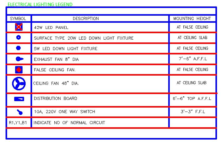
- Legend: the key that defines every symbol used on the drawings. Symbols differ between companies and standards, so the legend always overrides anything you have memorised.
- General notes and keynotes: general notes apply to the whole set (for example “all branch circuit conductors shall be copper, minimum 12 AWG”). Keynotes are numbered tags on a plan that refer to a note on the same sheet.
Also check the scale (for example 1/8″ = 1′-0″ or 1:100) and the north arrow, so you can measure distances and orient yourself against the architectural plans.
Electrical symbols
Electrical symbols are simplified pictures that stand for components such as switches, receptacles, lights, panels and protective devices. They let a designer show hundreds of devices on one sheet without written labels. Two main families are in use:
- US and North America: ANSI/IEEE 315 (schematic symbols) and NECA/NEMA architectural symbols used on building plans.
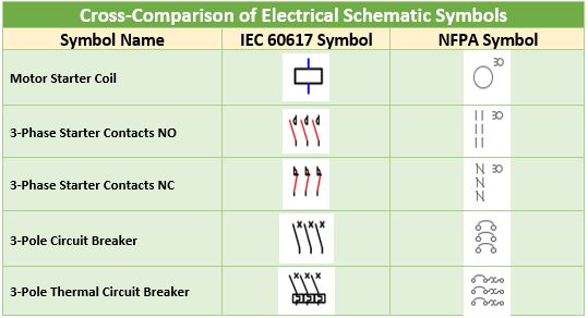
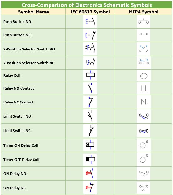
- International: IEC 60617, used in Pakistan, India, the UK, Europe and the Middle East (BS EN 60617 in the UK).
The comparison tables below show how the same component is drawn in the NFPA/ANSI and IEC styles, using symbols from the AutoCAD Electrical schematic library.
Common symbols on building electrical plans
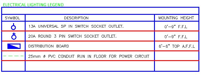
Construction drawings use a simpler set of architectural symbols to show where devices are located in a building:
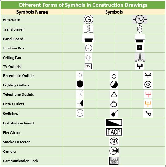
| Symbol (typical US plan) | Meaning | Notes |
|---|---|---|
| Circle with two parallel lines | Duplex receptacle (outlet) | GFCI, WP (weatherproof) or USB are written beside it |
| Circle with three lines or a triangle | Dedicated or special-purpose receptacle | Often labelled with voltage and amps, e.g. 240 V 30 A |
| S | Single-pole switch | S3 = 3-way, S4 = 4-way, SD = dimmer, SOS = occupancy sensor |
| Circle or rectangle with letter | Light fixture | The letter refers to the fixture schedule (type A, B, C…) |
| Shaded rectangle on a wall | Panelboard | Labelled with the panel name, e.g. LP-1 or DB-GF |
| Square with J | Junction box | |
| Arrow with numbers | Home run to panel | e.g. LP-1 / 3,5 means circuits 3 and 5 of panel LP-1 |
| Circle with SD / S | Smoke detector | Fire alarm devices are usually on a separate sheet |
| Triangle | Data or telephone outlet | Shown on low-voltage plans |
| Box with motor symbol (M) | Motor or equipment connection | Often tagged with the equipment number |
These are typical forms only. The legend on your drawing set is the final authority.
How to read a lighting plan
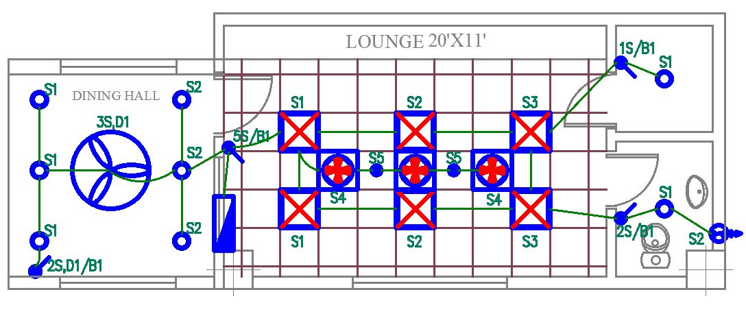
A lighting plan shows every light fixture, the switches that control them and the circuits that feed them, drawn over the architectural floor plan.
- Fixture tags: each fixture has a letter or code (A, B, EX for exit sign, EM for emergency) that matches the fixture schedule, which lists the make, wattage, voltage and mounting.
- Switch legs: a small lowercase letter (a, b, c) next to a fixture and the same letter next to a switch shows which switch controls which lights.
- Circuit lines: curved or straight lines between devices show that they are on the same circuit. Solid lines are usually concealed in walls or ceiling; dashed lines are often concealed in the floor or below grade (check the legend).
- Tick (hash) marks: marks across a circuit line show the number of conductors in that run. A common convention is short marks for ungrounded (hot) conductors, long marks for neutrals and a mark with a dot or circle for the equipment ground, but firms vary. If there are no marks, the minimum (two conductors plus ground) is usually assumed.
- Home run arrow: the arrow at the end of a run points back toward the panel and carries the panel name and circuit number, for example LP-1 / 7.
How to read a power plan and house wiring diagram
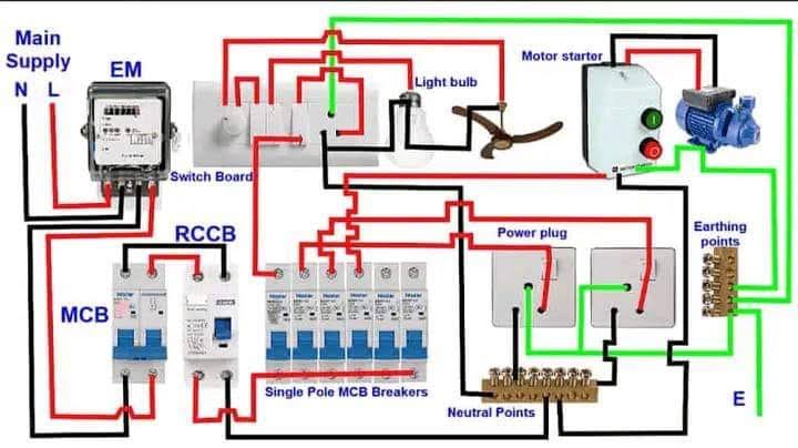
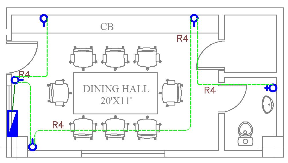
Power plans show receptacles (sockets), dedicated equipment circuits and the wiring routes back to the distribution board. To read them, it helps to understand how power reaches a room.
From the utility to the room
- Service: in the US, most homes get a 120/240 V single-phase service (two hot conductors plus a neutral); commercial buildings typically get 208Y/120 V or 480Y/277 V three-phase. In Pakistan, the UK and IEC countries, homes get 230 V single-phase or 400/230 V three-phase (three phases plus neutral).
- Meter and main panel: the utility meter feeds the main distribution board (also called the panelboard, breaker box or DB). It contains the main breaker, residual-current devices (GFCI/RCD) and branch circuit breakers (MCBs).
- Branch circuits: from the panel, circuits run to switchboards and then to each light, fan and socket.
Control devices and load devices
Room wiring has two kinds of device. Control devices such as switches and dimmers only interrupt the phase (hot) conductor, so they need only the phase wire. Load devices such as lights, fans, sockets and indicator lamps need both the phase and the neutral to complete the circuit, plus an equipment ground where required.
Reading the power layout
- Count the receptacles on each circuit by following the circuit line to its home run.
- Look for dedicated circuits: appliances such as air conditioners, ranges, water heaters, dryers and EV chargers get their own circuit, usually labelled with voltage and amps.
- Check the labels next to receptacles: GFCI (ground-fault protection, required in US kitchens, bathrooms and outdoors), WP (weatherproof), AFCI, and mounting heights.
- Read conduit and wire callouts. In US notation, 3/4″ C, 2#12, 1#12 G means a 3/4-inch conduit with two 12 AWG conductors and one 12 AWG ground. In IEC notation, 3C x 2.5 mm² + E means a three-core 2.5 mm² cable with an earth conductor.
Need to check the wire or breaker for a circuit you are reading? Use our wire size calculator, breaker size calculator and voltage drop calculator.
How to read a panel schedule
A panel schedule is a table for each panelboard listing every circuit. It is where the circuit numbers on the plans lead.
| Column | What it tells you |
|---|---|
| Circuit number | Matches the home run numbers on the plans. In US panels, odd numbers are on the left and even on the right. |
| Description / load served | For example “Receptacles – Kitchen” or “AHU-1” |
| Breaker (trip) size and poles | For example 20 A 1-pole, or 30 A 2-pole for 240 V loads |
| Load (VA or kW) per phase | Shows how the load is balanced across phases A, B and C |
| Panel header | Panel name, voltage (e.g. 208Y/120 V 3-phase 4-wire), main breaker or main lugs, bus rating, short-circuit rating (kAIC) and where it is fed from |
| Totals | Connected load, demand load and the resulting feeder current |
Cross-check that each breaker matches the wire size on the plan and that the panel’s short-circuit rating suits the available fault current. Read more about breaker breaking capacity (Icu and Ics).
How to read a single-line diagram (SLD)
The single-line diagram (also called a one-line diagram) shows the whole power system with one line representing all the conductors of a circuit. Read it from the top (source) down:
- Source: utility service, generator, or both with an automatic transfer switch (ATS).
- Transformer: rating in kVA, primary and secondary voltage, and impedance (%Z). Check sizes with our transformer sizing calculator.
- Main switchboard: main breaker rating, metering and surge protection.
- Feeders: each line to a panel is labelled with breaker size and cable, for example 225 A, 4#4/0 + 1#4 G in 2-1/2″ C or 4C x 95 mm² Cu/XLPE/SWA + 50 mm² E.
- Panels and loads: every downstream panel, motor and large piece of equipment, with its rating.
Learn how SLDs are designed in our guide: how to design an SLD of an electrical LV system. Our kVA calculator converts transformer and generator ratings to amps.
How to read fire alarm and public address (PA) layouts
Fire alarm and public address drawings belong to the low-voltage (signal and control) systems and usually have their own sheets and legend. The main fire alarm components shown are:
- Detectors: smoke, heat, multi-sensor, duct and beam detectors (beam detectors work with a reflector)
- Manual call points (pull stations)
- Sounders, strobes and response indicators
- Monitor, control and relay modules
- Sprinkler flow switches and supervisory devices
- Fire alarm control panel (FACP), power supplies and the emergency voice/communication system
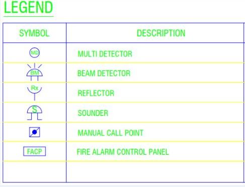
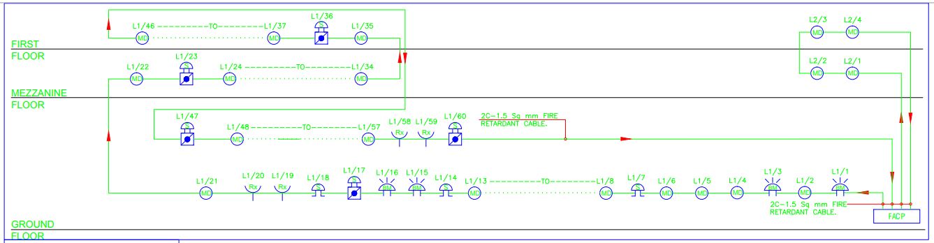
The fire alarm schematic shows how devices connect on each loop. The example below is an addressable system with two loops covering three floors, connecting the FACP, multi-detectors (MD), a beam detector (BM) with reflector (Rx), sounders (S) and manual call points (MCP).
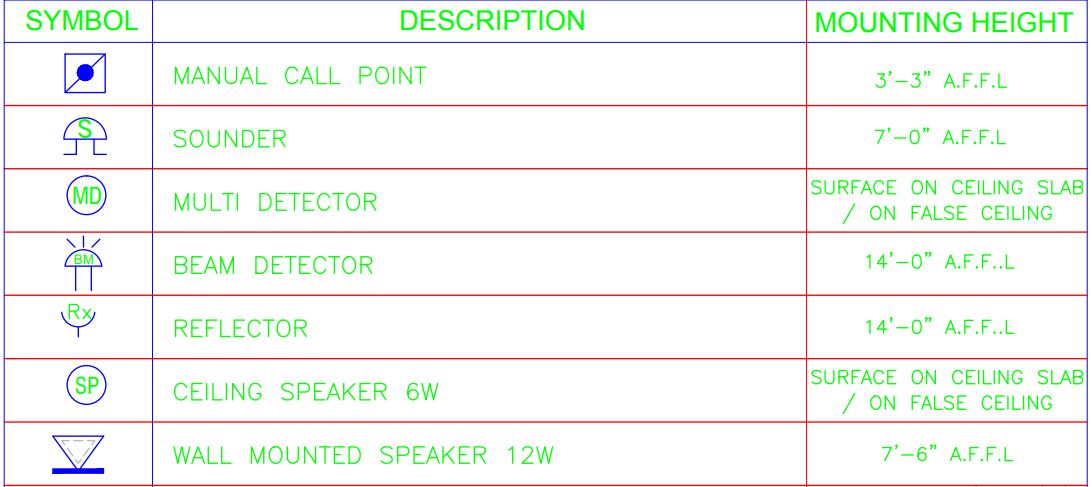
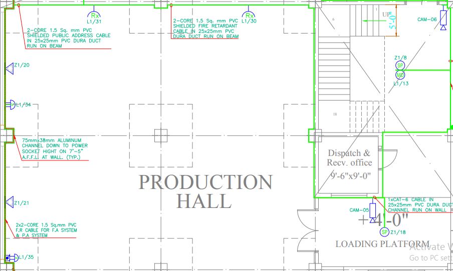
A public address layout shows the amplifiers, microphones, call stations and speakers (ceiling, wall and horn types) and the speaker zones. In modern buildings, PA and fire alarm are integrated so that evacuation messages play automatically, and both systems’ devices may carry addresses shown on the drawings.
For code requirements behind these layouts, see NFPA 72 fire alarm requirements and fire alarm system key concepts.
Checklist and common mistakes
- Reading an old revision. Always check the revision table and clouds first.
- Assuming symbols. Use the legend on the set you are reading, not one from another project.
- Ignoring general notes. They often set minimum wire sizes, conduit types and mounting heights for the whole job.
- Not tracing home runs. Every device should lead to a panel and circuit number that appears in the panel schedule.
- Forgetting other trades. Check the mechanical and plumbing drawings for equipment that needs a power connection.
- Scaling from a resized PDF. Use dimensions where given, or confirm the scale with a known dimension.
Frequently asked questions
How do you read electrical drawings for beginners?
Start with the title block and the legend, then read the single-line diagram to understand how power flows, the panel schedules to see each circuit, and finally the lighting and power plans, tracing each device back to its panel and circuit number.
What does a home run mean on an electrical drawing?
A home run is the circuit run from the last device back to the panelboard. It is shown as an arrow labelled with the panel name and circuit number, for example LP-1 / 7, meaning circuit 7 in panel LP-1.
What do the tick marks on electrical plans mean?
Tick or hash marks across a circuit line show how many conductors are in that run. A common convention uses short marks for hot conductors, long marks for neutrals and a marked tick for the ground, but the legend of each drawing set defines the convention used.
What is the difference between a single-line diagram and a wiring diagram?
A single-line diagram shows the whole power system with one line per circuit and focuses on ratings and how power flows. A wiring diagram shows every individual conductor and terminal connection for a specific piece of equipment or circuit.
Are electrical symbols the same everywhere?
No. North America uses ANSI/IEEE and NEMA-style symbols, while most other countries use IEC 60617. Even within one standard, companies customise symbols, which is why every drawing set includes its own legend.
What scale are electrical floor plans drawn at?
Building floor plans are commonly drawn at 1/8 inch = 1 foot or 1/4 inch = 1 foot in the US, and at 1:100 or 1:50 in metric countries. The scale is shown in the title block or under each drawing.
Conclusion
Reading electrical drawings is a skill built in layers: the title block and legend tell you how to read the set, the single-line diagram and panel schedules show how power is distributed, and the lighting, power and low-voltage plans show where everything goes. Practise by taking one circuit at a time and tracing it from the device back to the panel and up to the source.
Related guides and tools

A dedicated Electrical Engineer with expertise in ISO auditing and a strong passion for sharing insights into the electrifying world of design. With over 5 years of diverse experience, I’ve powered through projects ranging from the manufacturing industry to building construction. My skillset extends to automation building design, where my meticulous electrical drawings ensure precision and attention to detail.
Related Posts: