Code Requirement for Voltage Drop Calculations?
NFPA 72 2013 Edition Section 7.2.1 states that – “Where documentation is required by the enforcing authority, the following list shall represent the minimum documentation required for all fire alarm and emergency communication systems, including new systems and additions or alterations to existing systems.“, Within the list, you will find #7, Battery Calculations and #8, Voltage Drop Calculations.
Keep in mind that almost all fire alarm control panels are 24 volts DC. However, still there are few fire alarm control panels that works on 12 volt DC. Just remember that the calculations for NAC voltage drops are the same for these systems, however the cut off voltage for a 12 volt system will be roughly half that of a 24 volt system.
What is the reason for voltage drop calculations?
NAC voltage drop calculations are critical for determining if your notification appliances will in fact work with the provided head end equipment. (This is of course based on the installation contractor installing the system per plans and noted wiring distances). If you perform your NAC voltage drop calculations correctly at the time of design, you will know exactly how many remote power supplies and NAC circuits are needed as well as the wall space requirements and 120 VAC connections required by the electrical contractor. Keep in mind that this is a requirement of NFPA 72.
Voltage Drop Calculation Methods
There are primarily two methods to perform a NAC voltage drop calculation. These methods are better known as “Point to Point (PTP)” and “End of Line (EOL)”.
· Point to Point Voltage Drop requires much more math than the “EOL” method. However, the extra work pays off as this method is more accurate.
- Designers generally use this method with a spreadsheet as the math can become tedious
- This is the method typically used by panel manufacturers within their own calculation programs
- Since it is less conservative of the “EOL” method, it allows for more devices on a circuit.
- There are cases of a 30% difference between the PTP and EOL methods
End of Line method is the easiest, quickest calculation
- Can be done easily by hand or with a calculator
- Results are less accurate that provide lots of head room for future expansion
Starting Voltage and Cut-Off Voltage
UL (Underwriters Laboratories) 864, 9th Edition Standards for Fire Alarm Control Panels:
- All panels must have a demonstrated 20.4 VDC panel cut off voltage.
You may be asking, “Where did they come up with 20.4 VDC on a 24 Volt system?”
It is actually quite simple. 20.4 VDC is 85% of 24 VDC. Or like we stated earlier, there are a few 12 VDC systems floating around. In their case, the demonstrated voltage shall be 10.2 VDC. Once again, 10.2 VDC is 85% of 12 VDC.
Now, above we mentioned a term “Cut-Off Voltage”. All fire alarm control units (FACU) have and internal voltage drop. The voltage at the actual NAC output terminal is always less than 20.4/10.2 volts at cut-off.
- This amount of drop varies with every panel. The variance can be as much as .5 VDC to 2.5 VDC.
Keep in mind that this value is not often found within the panel documentation. I have found that the easiest way to obtain this value is to contact the panel manufacture and get it in writing.
You now may be asking yourself, “Why is it so critical that I get this value from the manufacturer and not just use the 20.4/10.2 value figured from the 85% set forth by UL 864 9th Edition?”
In order for your NAC voltage drop calculations to be precise and as accurate as possible based on the facts and information provided, you must use the specific panel/power supply terminal cut-off value.
How to determine your NAC Voltage Drop using the End of Line method:
Step #1
Firstly, Add up the total current draw for your entire notification appliance circuit. This is based on the manufacture, type (strobe only, horn/strobe, mini horn, audible level, wall, ceiling, etc.) Make sure to consult with the appliance documentation to get these figures.
Step #2
Secondly, Add up the total wire length for the run and multiple it by 2 (if class B). The 2 represents the number of conductors used in the run.
Step #3
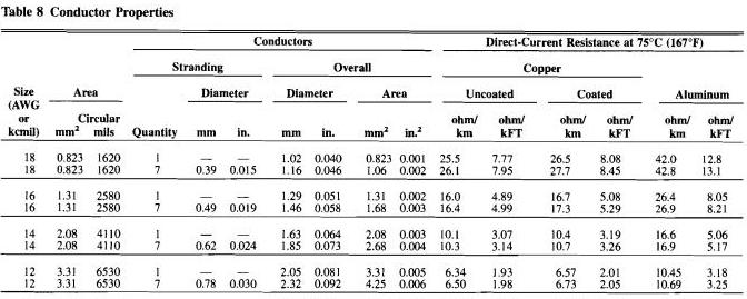
Thirdly, Multiply the total wire length times the wire resistance value per foot for a total circuit wire resistance. The wire resistance per foot can be found in Table 8 “Conductor Properties” in Chapter 9 of the National electrical Code.
Step #4
Fourthly, Using Ohm’s Law we know that Current (I) x Resistance (R) = Voltage (E). Simply take the total current found in step #1 and multiply it by the resistance found in Step #3. This will give you the volts dropped.
Step #5
At last, Subtract the volts dropped from the panel/power terminal cut-off voltage to obtain the voltage that will be supplied to the last appliance on the circuit. This value MUST exceed 16 volts. Keep in mind that this method is not as accurate as the Point to Point method. This method assumes that the voltage drop at each appliance will be the same when in reality, they are not.
Below is an example of an End of Line voltage drop calculation:
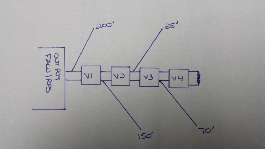
Diagram notes:
- We will assume that the terminal cut-off voltage is .5 volts below the 20.4 VDC giving us a voltage of 19.9.
- Use the wire lengths shown in the diagram
- V1=85mA / V2=75mA / V3=115mA / V4=100mA The circuit is using #12 AWG wire
- Use the Table 8 of the NEC (National Electric Code) provided previously in this document
Using the Diagram and notes above, can you provide the voltage drop for this circuit using the End of Line method? Give it a try and when you are ready move on to the next page where we will break it down for you.
End of Line Voltage Drop Calculation Break Down:
Step #1
Add up the total current for all four notification appliances within the circuit. We know that V1 = 85 mA, V2 = 75 mA, V3 = 115 mA and V4 = 100 mA. The total of all four of these is 375 mA.
Step #2
Add up the total wire length and multiply it by 2. We know based on the diagram that the first section is 200 feet, the second section is 150 feet, the third section is 25 feet and the final section is 70 feet. This totals up to 445 feet x 2 = 890 Total Feet
Step #3
We know from the Table 8 “Conductor Properties” we have a value of 1.98 Ohms/1000 feet of #12 AWG stranded uncoated wire. To find our resistance for our circuit simply take the total wire length (890 Feet) and divide it by 1000. This gives us a value of .89. Now take .89 and multiply it by the 1.98 value found in the NEC Table. (.89 x 1.98 = 1.7622 Ohms of Resistance)
Step #4
Using Ohm’s Law we know that Current (I) x Resistance (R) = Voltage (E). Take the total current found in Step #1 (.375) and multiply it by the total found in Step #3 (1.7622). .375 x 1.7622 = .660825 volts dropped.
Step #5
Finally, we need to subtract the .660825 volts from our terminal cut-off voltage. We know from the previous diagram and notes that we have a terminal cut-off voltage of 19.9 volts. 19.9 volts – .660825 = 19.239 Volts at the last appliance.

An experienced electrical professional having more than 8 years of experience of the industry in diverse fields of engineering including Electrical Design & Consultancy, Audit & Inspection, Execution of Construction Projects having expertise in designing of HighRise buildings, Residential & Commercial buildings, Offices, Schools, Restaurants and some Industrial projects
Related Posts:


")
